Directional control valve schematic symbol [diagram] pneumatic 3 way valve diagram 4 way 2 position valve schematic
4 Way 2 Position Valve Schematic
Solenoid valve way directional position pneumatic valves stcvalve Pneumatic symbols circuit valve position explained solenoid spring double return flow actuated path Valve position way control construction working
Pilot solenoid valve symbol at william reser blog
Mariners repository: hydraulics part 1[diagram] 3 way valve diagram Three way valve schematic3 way and 2 position valve.
T port and l port way ball valves differences covnaValves position directional positions ports clippard Way valves two valve spool control three flow four direction ports pressure rotary drawing port hydraulics other mariners repository configurations3v310: 3-way, 2-position directional solenoid valve.

4 way pneumatic valve schematic
Three way valve diagramHydraulic schematic diagram symbols Port and position of directional control valveOpen center valve schematic.
3 way manual valves • related fluid power3 2 valve schematic Way manual valve position valves control hydraulic fluid power directionalSolenoid valves types & functions instrumentation tools.

[diagram] 3 way solenoid valve diagram
Valve position wayPneumatic circuit symbols explained |library.automationdirect 4 way 3 position control valve working & construction youtube 720pHow to select electronic directional control valves.
Solenoid valves functions symbols instrumentationtools principle[diagram] wiring diagram 3 port motorised valve How to correctly use a 3 way valve in different applications.

4 Way Pneumatic Valve Schematic

3 Way Manual Valves • Related Fluid Power

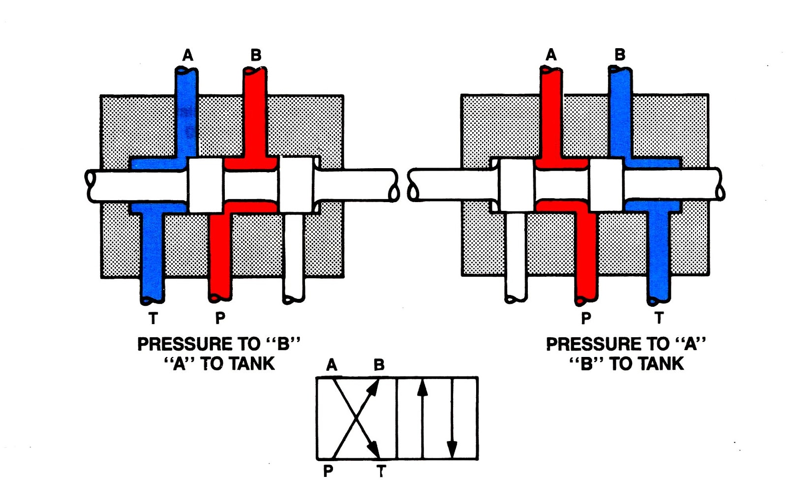
Mariners Repository: Hydraulics Part 1 - Direction Control Valves
![[DIAGRAM] 3 Way Valve Diagram - MYDIAGRAM.ONLINE](https://i2.wp.com/www.directmaterial.com/blog/wp-content/uploads/2014/04/three-way-ball-valve.jpg)
[DIAGRAM] 3 Way Valve Diagram - MYDIAGRAM.ONLINE

Directional Control Valve Schematic Symbol

Open Center Valve Schematic

3 WAY AND 2 POSITION VALVE

3 2 Valve Schematic

Solenoid Valves Types & Functions Instrumentation Tools